Stylistic Shell-Shaded Fur in Bloodelic
§ Intro
-
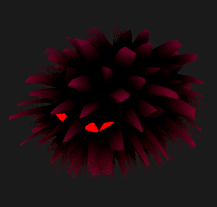
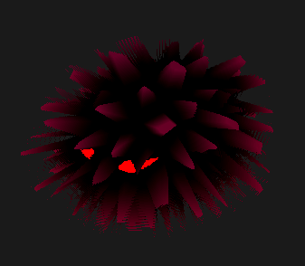
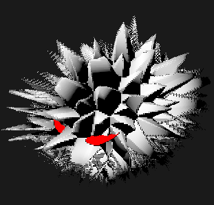
This walkthrough goes through implementing a ferro-fluid-inspired creature called King in the VGDev horror/turn-based strategy game Bloodelic
- For reference, Bloodelic uses Unity built-in render pipeline (specifically Unity 2022.3.16f1) for ease of shader scripting, and some techniques are specific for it
- Concepts should translate well to other engines and pipelines, and optimizations are definitely more available for something like Unity URP
-
This writeup is intended more as a collection of techniques than any particular "discovery", it will cover...
- Setting up shell-based fur rendering using shaders
- More advanced shader stuff
- Animating appearance using shaders
- Animating movement using C#
- Even more shader stuff, focusing on "GPU geometry" (By GPU geometry I mean noise and calculus tricks in the fragment shader, not vertex shader tech like GPU instanced grass)
-
As there are lots of different code interacting with each other, I recommend downloading the packaged project first and follow through the code dive
§ Shell Shading Basics
§ What is Shell Shading
This article by GiM studio and this video by Acerola on Youtube are both good introductions to the topic.
The basic framework for the code used in this writeup comes from the video.
§ Shell Setup: Mesh & Vertex Shader
-
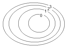
In shell-based fur rendering, the original shape (i.e. mesh) of a creature is covered with layers of very thin "shells"
-
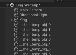
Each shell is its own mesh, copying the main body mesh (this supports skeletal meshes in theory but performance hasn't been tested)
-
Shells are numbered from inside to outside
-
Each shell is rendered with a specific instance of a shared material: our writeup will mostly be dealing with this material
-
-
The layout of shells in the game world is simple: each shell object exists on the top level without any parent, and they simply copy the transform of the player mesh
This allows the VFX code to be completely separate from logic code, as well as any VFX-spawned assets to be separate from the player object in the scene.
-
Note that each shell is slightly larger than the previous, but this isn't done using C# script, instead a displacement is computed in the vertex shader
-
The output definition for the vertex shader contains standard Unity lighting and coordinate information, as well as other information such as
shellHeightthat is packed together with existing variables to keep texcoord use reasonablestruct VertexOutputForwardBase { float4 pos : SV_POSITION; float3 uvh : TEXCOORD0; // uv | shellHeight float4 worldPos : TEXCOORD1; // world pos | light x /* Note directions are *linearly* interpolated in hardware meaning they lose magnitude in the fragment shader*/ float4 worldTangent : TEXCOORD2; // world pos | light y float4 worldNormal : TEXCOORD3; // world pos | light z /* Unity lighting, see built-in shaders for 2022.3.14, specifically VertexOutputForwardBase in UnityStandardCore.cginc */ float4 ambientOrLightmapUV : TEXCOORD4; // SH or Lightmap UV float4 eyeVec : TEXCOORD5; // eyeVec.xyz | fogCoord UNITY_LIGHTING_COORDS(6, 7) // Lighting channel + shadow channel /* Warn: starting here the tex coord count is over the SM2.0 limit of 0~7 */ // ex. if I add `float4 lightDir : TEXCOORD8` here Unity will give me a warning :/ };- The weird
| light ...comments will come in handy in a later section!- In essence, we are forced to use the extra space to store different things so that the code fits in legacy hardware
- The weird
-
As for the vertex shader itself...
VertexOutputForwardBase vp(VertexData v) { VertexOutputForwardBase i; UNITY_INITIALIZE_OUTPUT(VertexOutputForwardBase, i); i.uvh.xy = v.uv; // copies vertex UV to output // !important: compute shell height float spikeT = (float)_ShellIndex / (float)_ShellCount; float shellHeight = spikeT + 0.025; // add small bias for clipping issue i.uvh.z = shellHeight; // !important: offset vertex v.vertex.xyz += v.normal.xyz * _ShellLength * shellHeight; i.worldPos.xyz = mul(unity_ObjectToWorld, v.vertex); i.worldTangent.xyz = normalize(UnityObjectToWorldDir(v.tangent)); i.worldNormal.xyz = normalize(UnityObjectToWorldNormal(v.normal)); i.pos = UnityObjectToClipPos(v.vertex); /* Unity lighting, see built-in shaders for 2022.3.14, specifically vertForwardBase in UnityStandardCore.cginc */ i.eyeVec.xyz = normalize(i.worldPos.xyz - _WorldSpaceCameraPos); // ...orig: needed for shadow UNITY_TRANSFER_LIGHTING(i, v.uv); // inlined from VertexGIForward in UnityStandardCore.cginc, sets up global illumination based on project setting i.ambientOrLightmapUV = 0; i.ambientOrLightmapUV.rgb = ShadeSHPerVertex(i.worldNormal, i.ambientOrLightmapUV.rgb); UNITY_TRANSFER_FOG_COMBINED_WITH_EYE_VEC(i, i.pos); return i; }- Most of this stuff is standard (check the
!importantcomments for custom shell shading logic!) - What this achieves is offsetting each shell's vertex along the normal direction (i.e. outward away from the surface), meaning each layer is puffed up more than the previous
- Most of this stuff is standard (check the
-
-
Shell Setup: Fragment Shader
-
The main idea of the fragment shader is to divide up the 2D UV space of the mesh, and
discardareas you don't want on each layer of the shell, so that the layers beneath it can show through the gap-
An illustration of a very simple example is to draw "dots" on each shell, and those dots form cylinder-like shapes when shells connect together
-
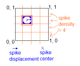
If we flatten the UV space into a square, the dots would look like this
- Note that everything too far from the "spike center" will be discarded!
-
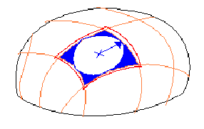
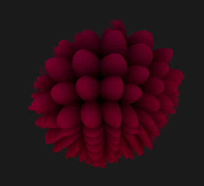
And on the blob-shaped model it will look like this
-
The example rendered result with 50 shell layers will look like this
-
-
The fragment shader itself is very straightforward, outside from the Unity lighting mess that I will omit for now...
float4 fp(VertexOutputForwardBase i) : SV_TARGET {

    float3 worldNormal = normalize(i.worldNormal.xyz);
    float spikeT = (float)_ShellIndex / (float)_ShellCount;

    // !important: cylinder masking math
    float2 spikeUv2 = i.uvh.xy; // spikeUv.xy; // 2 means 2D here, not that it is a second variable about this
    float spikeDensity = 20; // this will be replaced with a variable later, this is just for demo
    float2 spikeCenter = floor(spikeUv2 * spikeDensity) + 0.5;
    float2 spikeDistance = spikeUv2 * spikeDensity - spikeCenter;

    bool shouldDiscard = dot(spikeDistance, spikeDistance) > 0.1;
    if (shouldDiscard) discard;

    float3 spikeNormal = worldNormal; // ignore this for now, we'll come back to this later!

    /** Omitted...: it's all lighting starting from here, not very important for the shell rendering topic, study on your own! :) **/
}
For full info about the lighting section, please refer to the packaged code!
- One specific line I do want to highlight in the light logic is this
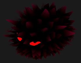
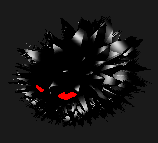
unlit = lerp(_BodyColor.xyz, _SpikeTipColor, spikeT * spikeT * spikeT);- It basically draws a gradient blending from the body color from black to red/magenta that you see in the screenshot
- Shadows are not included yet! We will come back to this later but the current light and dark contrast is purely done using color blending!
-
§ Stylized Geometry And Lighting
§ Spikes
-
Note that the original discard code, we use a boolean
bool shouldDiscard = dot(spikeDistance, spikeDistance) > 0.1- we can name this
0.1number the cutoff threshold, - Since all shell layers use the same
0.1number (named the cutoff threshold), they discard the same amount and the width of the cylinder never changes - Rather, we want top layeres to discard more than the lower layers so that the cylinder becomes sharper and sharper near the top
- we can name this
-
A simple solution is to just make the cutoff threshold stricter per layer
-
ex.
dot(spikeDistance, spikeDistance) > lerp(_SpikeCutoffMin, _SpikeCutoffMax, spikeT)- As in, the higher the layer is within the spike (
spikeTcloser to 1 than 0), the requirement for not discarding that pixel is harder to achieve, and so more of that layer is discarded instead of shown - (Note that I call the cutoff for the base of the cylinder to be
_SpikeCutoffMinregardless of whether it is smaller thanMax, and vice versa...)
- As in, the higher the layer is within the spike (
-
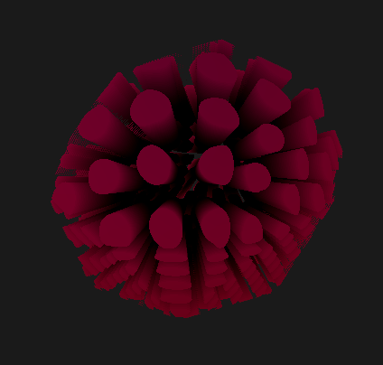
Here's what setting min to
0and max to0.5gives -
... and when max is larger than min, the cone shapes are flipped upside down
-
-
Because distance is a squared value, the "spike" actually renders as bumps with curvature matching the square-root graph
-
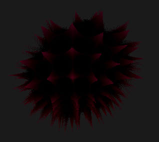
To fix this, we invert the discard condition and add a stylization parameter for more tweaking
bool shouldNotDiscard = dot(spikeDistance, spikeDistance) < lerp(_SpikeCutoffMin, _SpikeCutoffMax, pow(spikeT, _SpikeShapeStylizationFactor)); -
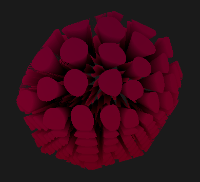
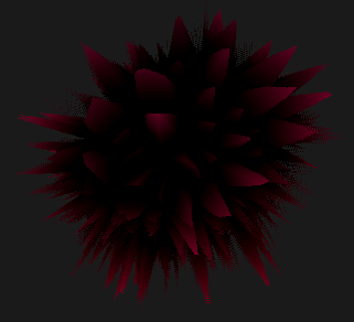
With
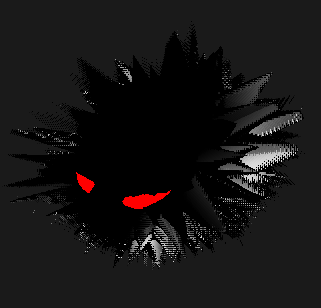
_SpikeCutoffMin = 0,_SpikeCutoffMax = 0.6, and_SpikeShapeStylizationFactor=0.7, the following spikes can be produced- Note that this picture looks darker, because more upper layers are completely dicarded
This shows one issue with shell shading that sometimes performance is wasted if parameters are not tweaked well: if all pixels in a shell is checked and then discarded, it's clearly more performant if the shell just wasn't there in the first place!
-
§ Voronoi Shaping
-
As much as we love cylinders and cones, we need an actual shape for the spike, and for this we just need to change the distance metric we're using
- Previously, we're using the distance from the center of each grid cell, resulting in a circle
- Instead, we can switch to a Voronoi distance (i.e. distance to the nearest point on a randomized grid) to result in a wonkier shape :)
- I will be using someone else's implementation and won't really explain all the code...
- (If you do want to compare with Ronja Tutorials' original code... two modifications I made are: 1) actually returning the min distance as an additional output, and 2) using another random hashing function from the Acerola vid)
-
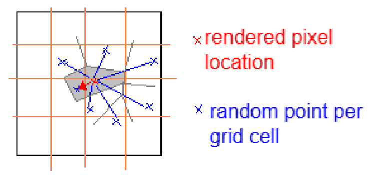
The flattened UV space looks something like this very rough sketch
- Notice that the distance from a pixel to its nearest point is not necessarily within the same grid as the pixel itself, this gives a lot of freedom for all sorts of wonky shapes to come out of this Voronoi thing
- By constraining how much each random point deviates from the center of its own grid, you can limit "how wonky" the resulting image is (i.e. the possibility of slim, slanted, and generally irregular shapes). The example code won't really show this but you can experiment on your own!
- Notice that the distance from a pixel to its nearest point is not necessarily within the same grid as the pixel itself, this gives a lot of freedom for all sorts of wonky shapes to come out of this Voronoi thing
-
Using the Voronoi distance, we can obtain spikes with non-regular edges
-
The code for using Voronoi is the following
float voronoi_squaredDistToCenter; // use squared distance to reduce some mult operations, since we don't actually need the accurate distance float voronoi_distToEdge; // this is computed via dot product so it's whatever float voronoi_cellIdx; // 0 ~ 1 random number based on the cell index's hash voronoiNoise( /* in params */ spikeUv2, _SpikeDensity, _AnimationTime, /* out params */ voronoi_squaredDistToCenter, voronoi_distToEdge, voronoi_cellIdx ); bool shouldNotDiscard = voronoi_distToEdge > lerp(_SpikeCutoffMin, _SpikeCutoffMax, pow(spikeT, _SpikeShapeStylizationFactor)); -
_AnimationTimewill be elaborated in a later section. In general, there is a lot of reasons why Voronoi is chosen, not just for its shape--we will go over all the other reasons in the rest of this writeup.
-
§ Height Mapping
-
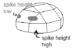
In addition to the spike masking, we also want to enable specification of spike heights over the entire mesh
-
This allows some areas to have no spikes at all, i.e. eyes
-
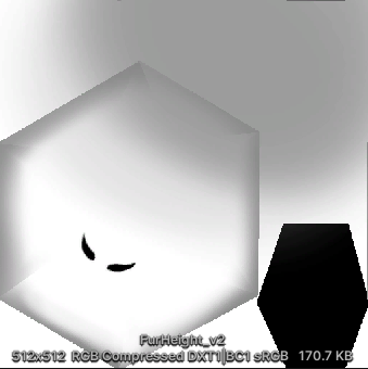
This texture is called the spike height map for the rest of this writeup
-
The example texture used is this, where the eyes and bottom of King are cropped out, and the fringes of the body and tail have slightly shorter spikes than the rest
-
-
To incorporate this texture, the vertex shader needs to be adapted to sample its value
float4 maxShellHeight = tex2Dlod(_SpikeHeightMap, float4(v.uv, 0, 0)); float shellHeight = spikeT * maxShellHeight.r + 0.025; // add small bias for clipping issue //shellHeight = pow(shellHeight, _ShellDistanceAttenuation); i.uvh.z = shellHeight; -
Now, the bottom spikes should be noticably shorter
-
We will be ignoring the inaccuracies this introduces to the mesh normals that were passed in, since offsets can now distort the surface of the mesh!
- It is definitely possible to recompute normals in the GPU, but this is out of the scope of this project...
-
To enable eyes and other strictly spike-less areas, we add this segment of code to the beginning of the fragment shader:
float4 maxHeight = tex2D(_SpikeHeightMap, i.uvh.xy); if (i.uvh.z > maxHeight.r) { if (_ShellIndex == 0) return float4(_EyeGlow, 0, 0, 0); discard; };-
This code samples the height map at a per-pixel precision instead of per-vertex, if the per-pixel height is lower, then render the glow color at layer 0 and force discard at every other layer above it
- Note that this is really more of a hack than an actual solution, working best for low-poly models with very clear cut boundaries. If the painted eye happen to overlap on a vertex, then the painted value will be directly sampled by the vertex shader, messing up the entire region!
-
-
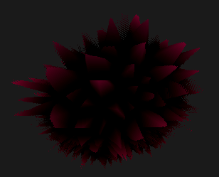
The result is the following...
§ Faking Gravity
-
There is an easy trick that, although not preserving any volume, could fake the look of fur "drooping" down
-
In the vertex shader, the following could be added to the offset calculations:
v.vertex.xyz += v.normal.xyz * _ShellLength * shellHeight - _ShellIndex * mul(unity_WorldToObject, float3(0, _ShellDroop, 0));- Note that the offset is in
-Ydirection since Unity's upward access isY
- Note that the offset is in
-
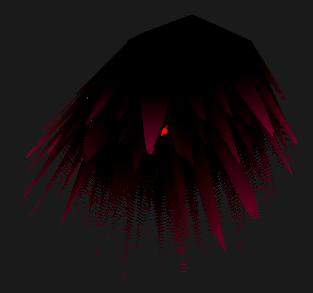
For a funny look, let's see what happens if
_ShellDroopis turned all the way up to 0.1 world units per layer... -
An issue with this parameter is it depends on the actual number of shell layers, which is a bad practice! So we switch to using
spikeTinstead, which guarantees to fall within a0~1range. -
Another issue is that the curvature is linearly applied, meaning each spike just gets hard-bent downards instead of curving "naturally"
-
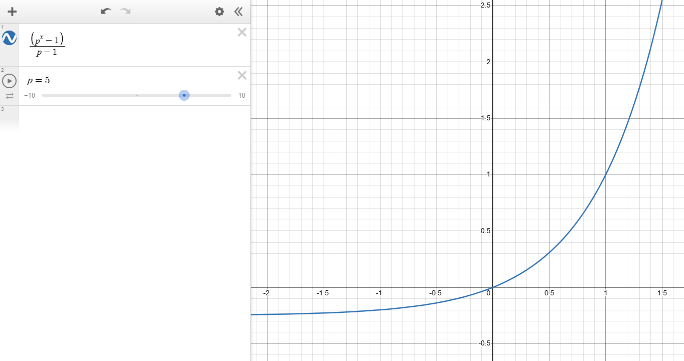
To fix this, we use a formula to further limit the effect of drooping when
spikeTis low, such as the following -
Most of this formula is just to keep the output in the range of 0~1 for inputs 0~1, the higher
pis the more the curve bends upward -
In code, this translates into
v.vertex.xyz += v.normal.xyz * _ShellLength * shellHeight - (pow(_SpikeDroopStylizationFactor, spikeT) - 1) / (_SpikeDroopStylizationFactor - 1) * mul(unity_WorldToObject, float3(0, _ShellDroop, 0));
-
-
Visualizing the fix, we can see that, higher droop factors (such as 3) will result in more bending for the same amount of droop offset
-
And lower droop factors (such as 1.01) will result in stiffer (i.e. straighter) droop offset while keeping offset amount the same at the end
Note an issue with this formula is it runs into divide by zero is droop factor is strictly 1! More weirdness happens when factor is less than 1 and even 0, but this is out of expected inputs anyway...
§ Making It Move (Pt. 1)
-
If you've used Voronoi nodes in Unity or other engine's shader library before, then you probably fiddled with its configurations and saw it wiggling and twisting around when the seed value changes, something like this...
-
This motion looks like a potential for driving ferrofluid-like movement, which is part of the reason Voronoi is picked out of a bunch of alternatives
-
To make this possible, we simply add time to the UV before it gets used for randomization, hooking it up to the
_AnimationTimevariable we mentioned earlier...// This is in the Voronoi.cginc file instead of the main .shader file, float2 voronoiCellPosition(float2 cell, float time) { return cell + abs(sin(rand2dTo2d(cell) * 2 + time)); } -
This is what it looks like in motion

§ Making It Move (Pt. 2)
The basics of this uses lerp smoothing, which Freya Holmer went through in this video. She has some neat visualizations for why the technique is prone frame-dependence.
Due to the original code being written in Unity Burst-compiled jobs, only pseudocode would be provided for this section. For full code, please refer to the full example in the final section, as well as code snippets in the Burst section
-
In the very first section we mentioned that all shells copy from player transform...
- This means as soon as the player object moves, all of the shells instantly teleport to the same location, which looks unnatural
- Instead, we want a "dragging" effect where higher-layer shells should follow the movement of lower-layer shells
-
Consider all shells numbered from
0toN-1, we record the current transform of each layer, including the scale, rotation, and translation -
At each frame, shell
iinterpolates itself towards shelli-1(with0snapping to the player object itself) by some factor, this "lerp smoothing" is something commonly done for cameras and etc. -
Combined, this forms a "inertia" effect where the tip of the fur "smoothly follows" the inner body
- Exaggerating the effect to demonstrate the "following"...
-
Translation
-
Rotation
-
- Exaggerating the effect to demonstrate the "following"...
-
The implementation is very simple, with the following pseudocode
on frame: for i from 1 to N: int prev = max(0, i-1) s[i].translate = lerp(s[i].translate, s[i-1].translate, kTranslate) s[i].rotation = slerp(s[i].rotation, s[i-1].translate, kRotation) s[i].scale = s[0].scale // this is purely for the style of animation, you can lerp if you want to -
Note that we are already introducing two forms of frame dependence... in the following sections we go over each.
§ Propagation Frame Dependence
-
To describe propagation, we first introduce the view of an ideal animation:
-
Suppose the player teleports X distance away form the current location and then stays perfectly still, the shells should follow one by one, until when the animation terminates by the time the last shell is approximately "at" the teleported location.
-
The more shells there are, the longer this ideal animation will take, since change propagates throughout the shells, it simply takes more frames for the outer shells to "notice" the movement from inner shells.
-
To illustrate this, we tweak the shell count up without changing any stylistic paramters and see what happens...
-
-
But why is this a bad thing, don't we want to tweak how the animation looks anyway?
- Consider that you want a high quality, RTX4090-worthy setting with 200 shells, and a mobile setting with 20 shells. Unfortunately, every animation on the high quality setting now takes ~10x times as long!
-
The solution is to subdivide the shell layers into normalized animation shells (short as a-shells for the rest of this writeup)
-
ex. If there are 20 shells but only 10 a-shells, then two shells will map to one a-shell during animation logic.
-
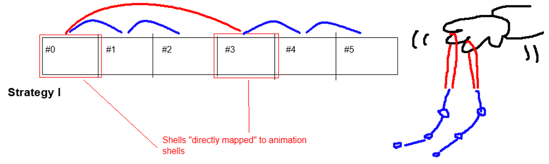
The pseudocode is still very simple:
on frame: for i from 1 to N: let mappingGroupCount = (numShells // numAShells) let excess be i % mappingGroupCount // this shell is directly mapped to an a-shell if excess is 0: j = max(0, i - mappingGroupCount) // this shell should snap to its previous shell, which *eventually* reaches a shell snapped to an a-shell else: j = i - 1 // "Strategy I" // ... same code as before, but lerping towards j instead of i - 1 ... -
To better illustrate the "Strategy I" mentioned above...
-
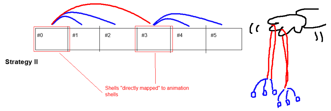
Now, there is an alternative "Strategy II" that does
j = i - excessinstead. Why? If each a-shell is mapped to a lot of shells, then this propagation issue that motivated the code edition manifests within each mapping group!- The tradeoff when adopting II instead of I is that the smooth motion within each mapping group is sacrificed, since all indirectly-mapped shells are forced to "snap" to the directly-mapped shells
- However, this actually isn't that noticeable, so we will be using strat II for thee rest of this writeup :)
-
-
With a-shell count separated from shell count, we can now tweak animation feel without affecting the render quality
- For dramatic, slow propagation, use a higher a-shell count
- For snappier, shorter propagation, use a lower a-shell count
For both, there is still obviously a constraint that a-shell count must be less than shell count! Otherwise it's as if we didn't make any change. If you want slower animation that requires an a-shell count above your maximum acceptable shell count, turn down the responsiveness instead!
§ Interpolation Frame Dependence
- Lerp smoothing is inherently exponential. Consider the per frame change
dx/dt = k(y-x),dx/dthas a componentkxthat is proportional tox, meaning the formula directly describingxincludes an exponential.For a non-calculus explanation, watch the Freya Holmer video mentioned beginning of this section
- Consider the most common example of exponential--the compound interest:
- Having variable framerate is equivalent to "receiving fixed interest rate at uneven periods of time", resulting in different interest earned (i.e. visual changes computed)
- Consider the most common example of exponential--the compound interest:
- To properly fix this issue, the lerp factor will need to be exponentially scaled against frame length
- But... since this is just a demo project, we will just run everything in Unity's
FixedUpdateand hope it actually keeps up :)
Another reason for not fixing this is because of how zoomed out everything is in the actual game, compounded on the fact that the distances between shell layers are simply very small! For this reason, this second type of frame dependence is way less noticeable than the first.
- In the full code, you will see two
...Responsivenessparameters, these are for tweaking stylistics, not for completely fixing the frame dependence! - The responsiveness parameters work by giving "a sense of physical time" to the animation code without completely fixing everything, for each
kin the pseudocode above, replace them withresponsiveness * deltaTime- The intuition is that, at least for an ideal animation with a fixed endpoint for interpolation (and consisting of only two layers!), the length of that animation is fixed since after
1 / responsivenessseconds it is guaranteed for any interpolation to finish
This is different from the real lerp fix; the real fix deals more with retaining the same "feel" from frame to frame by having a mathematically correct lerp factor.
- The intuition is that, at least for an ideal animation with a fixed endpoint for interpolation (and consisting of only two layers!), the length of that animation is fixed since after
§ Bonus: Unity Burst
I originally planned to go through all of the code changes, but this is more than 2 lines of code, so... check out the packaged code:)
For actually helpful information, see this article and this other one by Catlike Coding.
-
As a general summary, these following changes were done to cut down on repeated calculations and eliminate branching
- Move the index calculation out of the loop, and use
NativeArrays andUnity.Mathematics.mathfunctions - Make sure to use un-clamped versions of
lerpandslerp, which are defaults in Burst math but not regular UnityMathf- Make sure the lerp factors are already clamped to
0~1when passed to lerp
- Make sure the lerp factors are already clamped to
- Use persistent arrays instead of re-allocating
- Move the index calculation out of the loop, and use
-
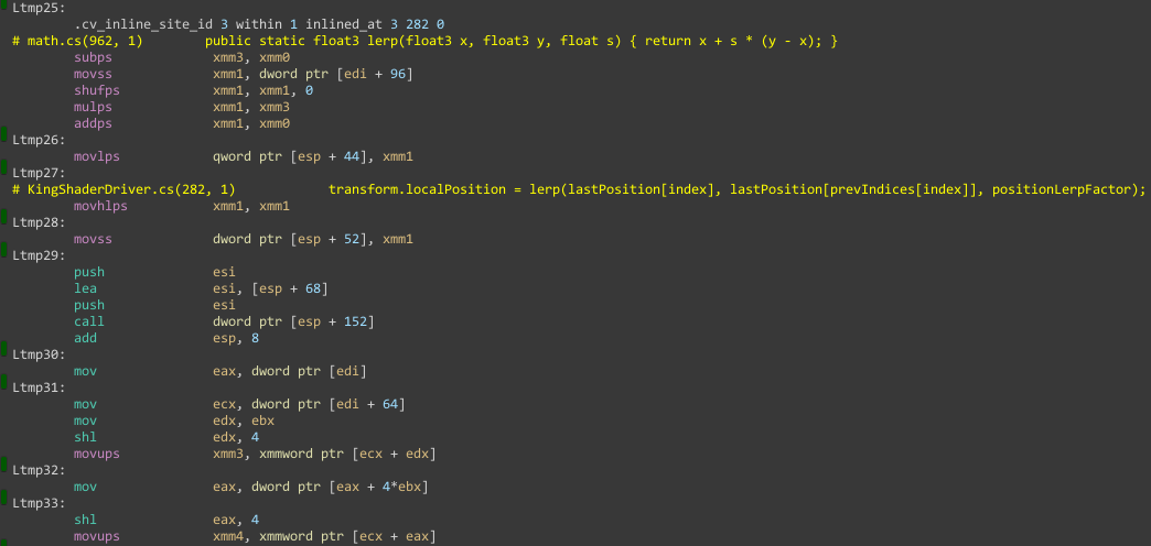
The end result can be seen in the Burst assembly inspector. Code performance isn't measured as this is really just an exercise, but we do se SIMD instructions so at least something is working! (on the left,
...psmeans packed SIMD and...ssmeans scalar SIMD, both are parallel, i.e. good) -
There are other tricks as well, such as turning safety check off
- As our
jindicies are always valid, we don't need array access to be checked ;)
- As our
-
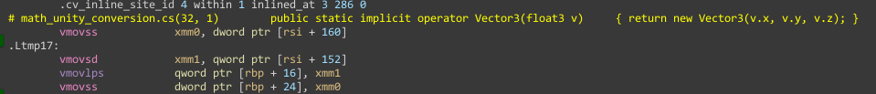
Although there seems to be one remaining issue, that being data-type incompatibility...
- The
TransformAccessclass we are using in the Burst job hasVector3as its type instead offloat3, and the assembly code seems to be doing some kind of manual object creation (and then copying over 3 floats over separately, see theqwordat+16and thendwordat+8...)
- I suppose this kind of conversion will have to happen eventually since the
Transformclass doesn't use SIMD types anyway...
- The
§ Light and Shadow
§ Approximating Geometry
-
Returning to our fragment shader, add some maths to compute more geometric descriptions of the current pixel that will be helpful later
float3 worldNormal = normalize(i.worldNormal.xyz); float3 worldTangent = normalize(i.worldTangent.xyz); // We assume that normal and tangent vectors still make sense after interpolation, and we *force* bitangent to be perpendicular to those two float3 worldBitangent = cross(i.worldNormal, i.worldTangent); // Technically we could be more precise and do worldTangent = cross(worldNormal, worldBitangent) * eitherNegativeOrPositive // this would make sure the normal vector is also exactly orthogonal to the normal, which could also be lost during interpolation // I'm skipping it cuz it doesn't feel that necessary :/ float3x3 worldToTangentFrame = inverse(worldTangent, worldNormal, worldBitangent);-
For now, the only thing that matters is the tangent, normal, and bitangent are three unit vectors mutually perpendicular to each other
- If we want to describe any other 3D vector, we can use a combination of these three vectors
aT + bN + cB. (To find these three multipliers we can use matrix inverses, as the rest of this sections will show.)
- If we want to describe any other 3D vector, we can use a combination of these three vectors
-
-
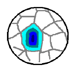
We have been using Voronoi noise, specifically a distance function, to generate spike shapes
-
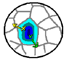
Consider a Voronoi cell mapped to a mesh, with distance from the cell's point marked in blue, in the order of "lighter > darker"
-
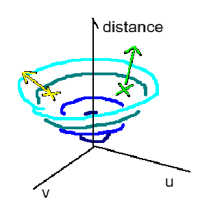
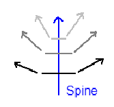
The gradient of such distance on a point is a direction that follows the direction of the "most dramatic increase" of distance
-
A common analogy of the gradient is a "hill" or "valley", we can visualize it in UV space
-
-
-
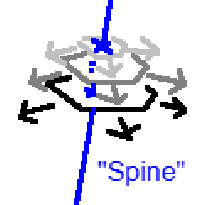
Notice that the gradient direction always pokes outwards from the "spine" of each spike, if we could find the gradient, then we can approximate a normal vector pointing out of the spine's geometry
-
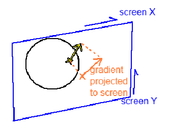
To find this gradient direction, we first find it's projection on the screen
-
This can be done using HLSL's derivative functions
ddxandddyfloat2 spikeGradientScreenspace_Round = float2(ddx(voronoi_squaredDistToCenter), ddy(voronoi_squaredDistToCenter));- Note that we are calling this "round", because the distance from the center radiates outwards from the center, looking round in UV space
-
To accompany this "round" metric, we also have a "square" metric that is based on the distance to the nearest edge
float2 spikeGradientScreenspace_Square = -float2(ddx(voronoi_distToEdge), ddy(voronoi_distToEdge));- This is
distToEdgemeasure is basically free as the Voronoi function already calculates it! - Just be careful that this needs to be negated, since distance to edge increases from the edge to the center, instead of the other way around
- This is
-
An artistic parameter is used to blend between round and square-looking lighting
float2 spikeGradientScreenspace = lerp(spikeGradientScreenspace_Square, spikeGradientScreenspace_Round, _SpikeShadowSmoothnessFactor);
-
-
Then, this screen space 2D vector needs to be converted to a 3D vector in world space
- This is done using existing matrices provided by Unity:
float4 spikeGradientWorld = mul(UNITY_MATRIX_I_V, float4(spikeGradientScreenspace, 0, 0)); - We also find the
a b cmultipliers mentioned before by converting this world space 3D vector into the tangent framefloat3 spikeGradientTangent = mul(worldToTangentFrame, spikeGradientWorld.xyz);
- This is done using existing matrices provided by Unity:
-
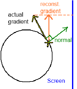
Now, due to the angle between the mesh and the screen, this reconstructed 3D vector wouldn't really line up with the actual gradient vector
-
Specifically, part of the reconstructed gradient is parallel to the normal of the mesh (i.e. along the spine of the spike)
-
To remove this part and arrive at the actual gradient vector, we do the following:
float3 spikeGradientWorld_Clipped = spikeGradientTangent.x * worldTangent + spikeGradientTangent.z * worldBitangent; float3 spikeNormal = normalize(spikeGradientWorld_Clipped);- Notice that we didn't include
worldNormal, this is because we are ignoring it!
- Notice that we didn't include
-
-
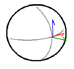
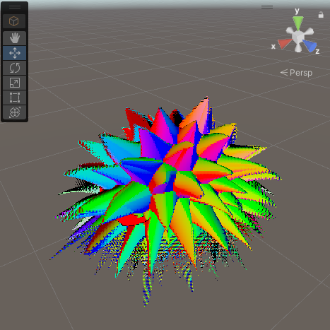
To visualize what the effect is, we directly return this normal as the color. Note that the colors line up with the color of the axis on the top right!
-
After all that, we actually need to add some normal direction back right after removing it completely, the reason being the actual curvature of the spike we're trying to simulate
-
We add yet another parameter to control this:
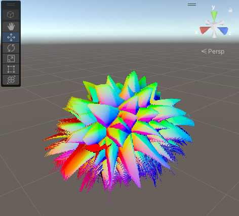
spikeNormal = normalize(lerp(spikeNormal, worldNormal, spikeT)) -
Again, visiualizing the normals, we see that the colors change way less dramatic now, this fixes the issue where one side of an entire spike lights up
-
-
Visualizing normals may still be too abstract. To see the point of all the math, this is what the lighting looks like if we just find the Lambertian lighting factor using the following code...
float3 lightToObj = normalize(-_WorldSpaceLightPos0.xyz); float rawNDotL = -dot(lightToObj, spikeNormal); // <-- our spike normal is used instead of the mesh normal! return saturate(rawNDotL);-
Note that
_WorldSpaceLightPos0isn't actually a position! Unity does this weird thing where the first directional light in the scene is called the "main light", and thatposvariable records its world space direction inxyz, plus the depth inw.- For additive passes with point lights, we will be computing light direction manually in the vertex shader
-
With this in place, it is hopefully more clear why the gradient styles are named as such...
-
Fully square gradients, with normal smoothing
-
Fully round gradients, with normal smoothing
-
Fully square gradients, without normal smoothing (notice the tip of the spike stays sharp-looking!)
- Note that no normal smoothing might look more neat here, but there will be reasons for normal smoothing coming up really soon...
-
-
Now, we upgrade from Lambertian to "Blinn-Phong" by adding specular lighting
float3 worldCamForward = unity_CameraToWorld._m02_m12_m22; float3 halfway = normalize(lightToObj + worldCamForward); float specularT = max(-dot(spikeNormal, halfway), 0); float specularAmount = _ShellSpecularAmount * pow(specularT, _ShellSpecularSharpness); -
Visualizing
specularAmountwill explain why normal smoothing is needed-
Note that without smoothing, spike normal always goes along the mesh surface by default, resulting in a ring of specular highlights
- Plus, the normal does not change along the spike, meaning when that "side" of the spike faces the light, the entire side lights up
-
Compare this to much less harsh highlights when smoothing is added...
-
-
Finally, we tweak the parameters a bit and get the following...
§ Problems With Built-in RP
While Unity Built-in Render Pipeline provides the best comfort for shader coding, it does not provide enough support for adding custom stages.
In the following sections, we will be re-computing everything at every stage. You can check for this in the packaged code.
It could be better to store the Voronoi data and etc. in textures and buffers (on the GPU end) instead of re-computing everything at every stage.
Anyway... prepare to witness the pinnacle of anti-DRY code in the sections below :)
§ Unity Shadow Jank
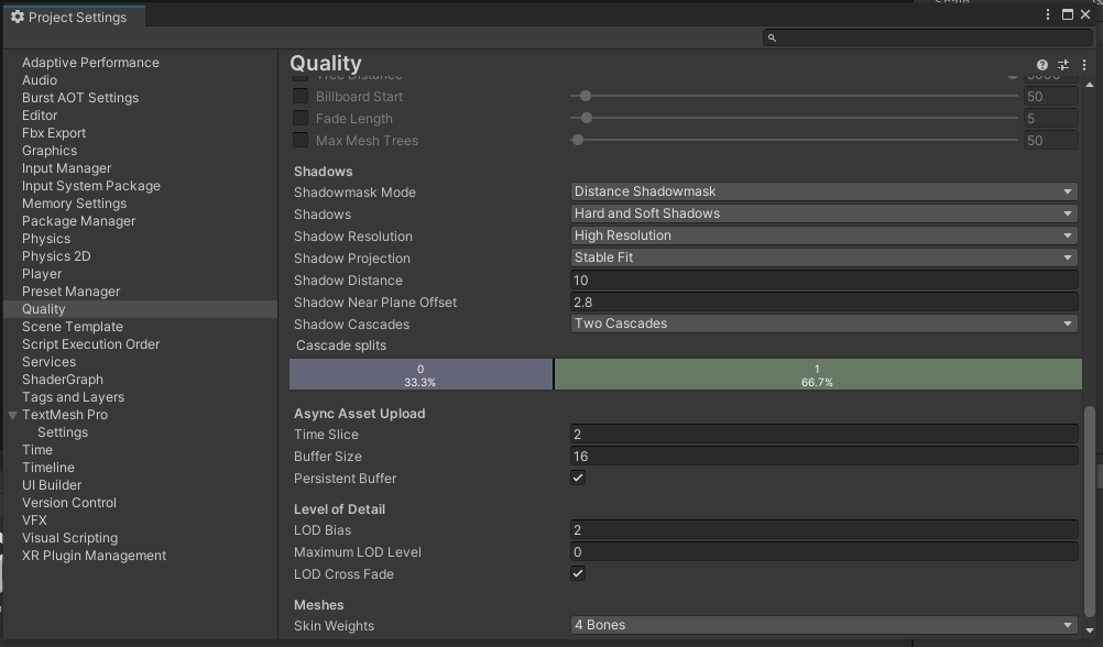
Please make sure to use the following project settings for shadow to make sure best replication!
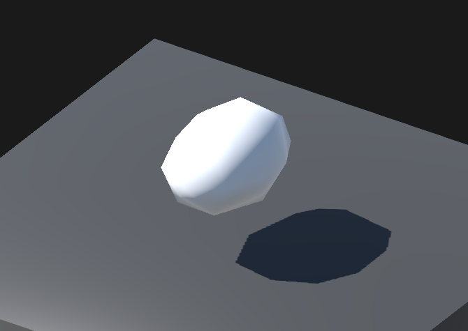
When your settings fit the above, the shadow demo scene should look something like this in the game mode preview with a sharp shadow outline
-
To toggle shadows on and off, please use this
shells cast shadowssetting without entering play!- When off, the original round mesh is used to cast shadow, while the shells do not cast shadow, vice versa
-
There really isn't anything technical about shadow...
- In general, just run the geometry code again.
- When you
discardin the previous code (the forward base pass), alsodiscardin the shadow caster pass - When you
returnin the previous code, call theSHADOW_CASTER_FRAGMENT(i)macro, which just means "this pixel is actually relevant for shadow casting"
- When you
For more info about shadow caster passes, see this article
- In general, just run the geometry code again.
-
You should see something like this when playing the demo:
-
What's the cost? Enabling shadow casting adds one shadow caster per shell to the scene, which may or may not be a performance issue...
- On my laptop, rendering 1080p drops from ~90FPS to ~80FPS when enabling shadows for 40 shell layers
- Interestingly enough, the frame rate maintained constant for soft shadows
- You will have to decide if shadows actually look good enough to warrant this performance drop...
§ Additive Lighting Jank
-
For the additive lighting demo, we use two lights instead of one, the additional being a point light
- Note that because the forward base pass only supports direction lights, any point light support must go through this additive pass!
-
In summary, we run a the exact same code as the forward base pass, just using different light computations
-
Specifically, the light direction needs to be computed and then packed in the vertex shader
// see vertForwardAdd from UnityStandardCore.cginc float3 lightDir = _WorldSpaceLightPos0.xyz - i.worldPos.xyz * _WorldSpaceLightPos0.w; #ifndef USING_DIRECTIONAL_LIGHT lightDir = normalize(lightDir); #endif i.worldPos.w = lightDir.x; i.worldTangent.w = lightDir.y; i.worldNormal.w = lightDir.z;- Note the
i.variable.w, this is the texcoord packing mentioned all the way in the beginning of this writeup
- Note the
-
... paired up with changes in the fragment shader
UnityLight mainLight; mainLight.color = _LightColor0.rgb; mainLight.dir = normalize(float3(i.worldPos.w, i.worldTangent.w, i.worldNormal.w)); #ifndef USING_DIRECTIONAL_LIGHT mainLight.dir = NormalizePerPixelNormal(mainLight.dir); #endif -
This code is just straight up copy pasting Unity's built-in shaders, for more unexplained info you'll have to read their source...
-
-
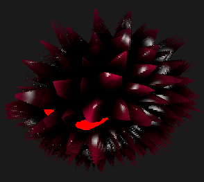
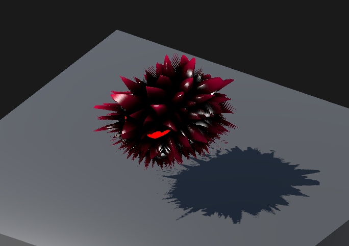
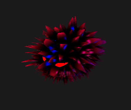
The end result is King can now be lit by multiple lights! In a month-themed style :)
- Note that the rings of specular lighting occur at different locations since lights come at different angles
§ Packaged Example Code
- Clone the repo
§ Trouble Shooting
- Make sure the project is using 3D built-in render pipeline in Unity (preferably 2022.3.16f1)
- Make sure you have installed the following packages
- Burst (reference version: v1.6)
- Cinemachine (reference version: v2.9)
- ShaderGraph (reference version: v14.0)
- If you want to check the shadow demo, please use the settings detailed in the shadow section
§