Sky Cylinder Rendering in Unreal
§ What and Why?
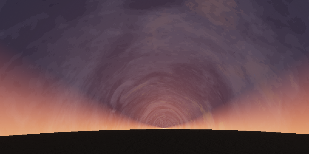
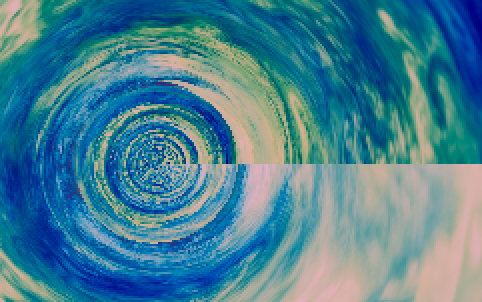
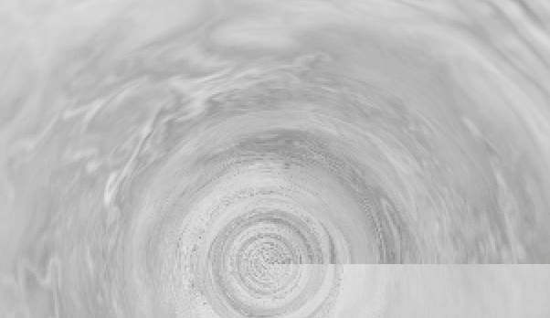
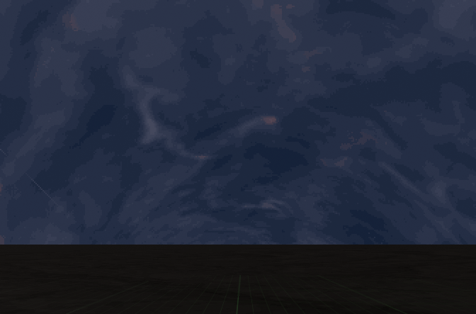
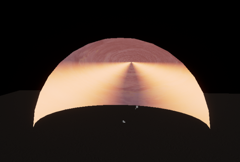
- Currently video preview is not implemented yet, so here's a still picture of the result
Ha! It is now after half a year :)
-
The cylinder is a trusty shape when needing to repeat a texture that is not specifically made for cube-mapping / sphere-mapping
- Compared to a "sky plane" the cylinder covers all view angles instead of just when looking up
- Moving the texture along the cylinder is relatively easy using nothing but only coordinate offset
- In prospective projection an infinite cylinder converges to a point, meaning further things are smaller
- This effect is useful until it actually just everything converges to a point and it becomes more of an issue than a feature
- The mesh for rendering the cylinder does not actually need to be a cylinder
- In fact we use an inverted sphere to render the cylinder! (this is because we solely rely on the view direction to decide what the sky looks like)
-
The main issues of this technique are
- Uniform rolling for all angles is un-natural and gives it a cardboard look
- Transition from cloud to horizon is abrupt and it really shows when there is nothing masking it
-
However the technique is surprisingly usable when
- The game is mostly top-down / bottom-up and the horizon is not seen
- The horizon is hidden behind things like skyline / vegetation
-
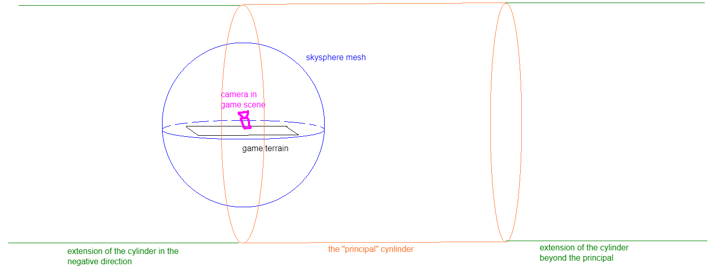
To further illustrate the concept, here is a "view" of the cylinder in the scene itself, relative to the actual mesh that is used to "render" it
-
Typically the imaginary cylinder is set to be larger than the mesh itself
-
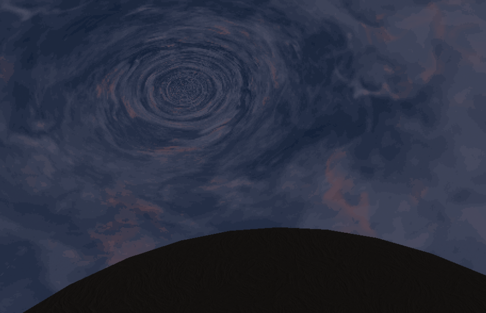
A particularly interesting result of using a sphere is you get a curved "horizon" whenever looking from an elevated angle. This isn't actually in the game as the camera for the main menu shot always looks upwards, but still kinda interesting nonetheless.
-
Notice the point in the center of the cylinder, this is what I meant earlier by "point of conversion"
-
The following assumes a +Z up, right-handed coordinate. You may need to adapt to your engine of use.
§ A Simple Implementation
§ The Omissions
- As I am only making the shader for a still shot in the main menu, the implementation below will be ignoring
- Accounting for camera position and using it to create parallax effects (rather than just the angle of the view direction)
- The issue of having everything converge at one point
- This can be hidden by a trick introduced later but not completely solved
- The above are, as all good books say, left as an exercise for the reader :)
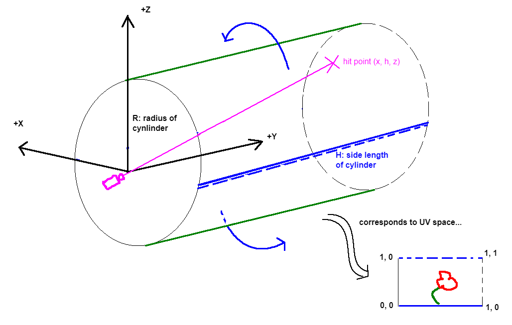
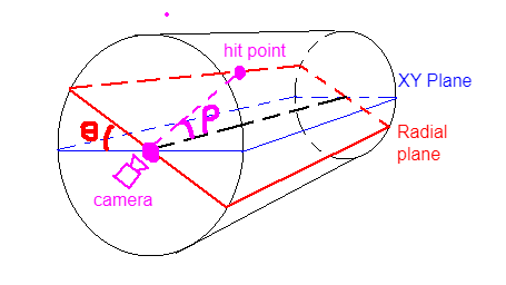
§ Cylinder Raycasting
-
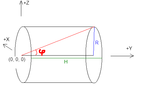
Define the principal cylinder as having its base on the origin
Rdenotes the physical radius of the cylinder (in engine-defined units)Hdenotes the total height of the cylinder (in engine-defined units)phidenotes its characteristic angle (in radians, since we're working with HLSL)
-
Note we can omit
HasR/H = tan(phi). This relation is basically the only math ever needed in this shader!- We can also omit
Rand just use some unit cylinder withR=1, but keeping theRallows for adding parameters to this model based on actual physical measures (as long as the unit is consistent withR's unit)
- We can also omit
-
Define the view ray
vas the vector from the camera to the world space location of the skysphere mesh (or whichever mesh you use, it work be exactly the same!)- In our case, it is sufficient to take the world space position directly as the view ray, as the camera is always assumed to be at the origin
This will need to be changed when implementing parallax
- The normalized view ray is
vn = normalize(v)
-
Define a plane such that it includes the
(0, y, 0)line and also the view ray. We call this the radial plane.- Let
thetabe the angle this radial plane makes against theXYplane - Let
rhobe the angle the view vector makes against the line of intersection between the radial and the XY plane (in this case just the Y axis)
- Let
-
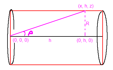
Imagine a point traveling out of the camera along the view ray, with position
p(t) = vn * t. We know that at some pointplies on the wall of the principal cylinder or some repetition of it. Let this point bep(t_hit) = (x, h, z)-
Note that this trail combined with the Y axis always draws out a right triangle on the radial plane, with
R/h = tan(rho) -
One problem arises is the asymptotic behavior of
tan, which can be handled, but the result is barely visible after scaling up the rendering to2x2per pixel- (Notice the slightly lighter arc than surroundings)
-
This problem could be fixed by just checking that the
absof thetanresult is less than some arbitrarily small number (like0.001f), if so replace it with a right angle instead ofNaN
-
-
And that's it! The rest is just converting this geometry into uv coordinates for sampling the texture, in particular...
- Let
U = abs(h) / Hbe one axis, andV = atan2(z, x)be the other. Ucurrently ranges from0to positive infinity, which we useu = frac(U)to reduce to the range[0, 1)Vcurrently goes from-PItoPI, so we remap into(v=abs(V/PI)+1)/2so it also fits within[0, 1]
- Let
-
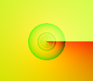
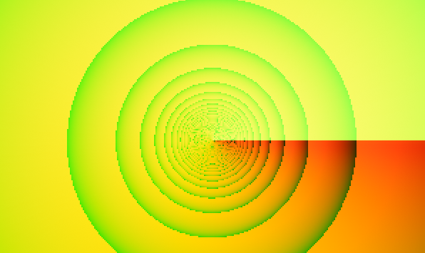
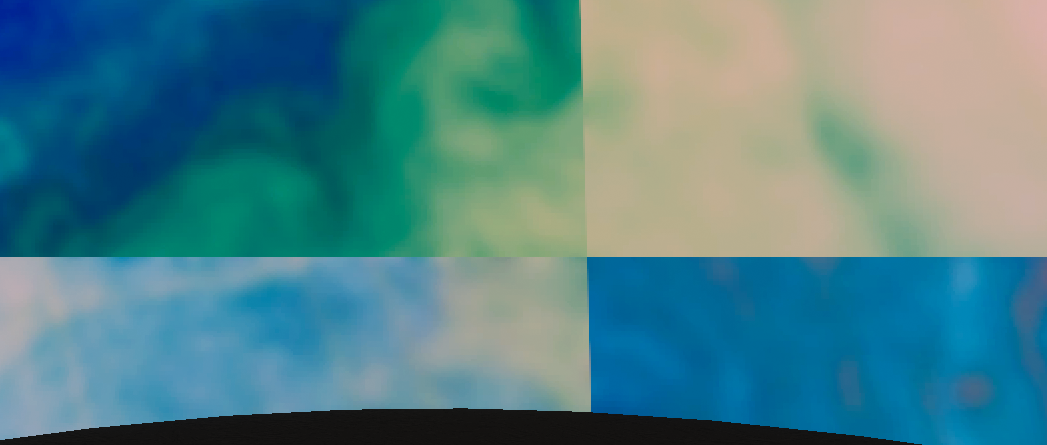
We print this
uvto see what we have at this point...-
phi = 0.1 -
phi = 0.5 -
Notice that
phidecreasing fromPI/2to0will stretch the cylinder out. Ideally you fitphiso that the2 * PI * R = H. I'm just pickingphi = 0.1since it looks good enough :)
-
-
Something to note here is
Rdoesn't really seem to do anything at all, sincephiby itself defines the shape of the cylinder. You can replaceRwith1in the above and everything will work the same. The reason we useRis in the following sections... -
Now if we directly use
uvto sample a texture, it'll look absolutely horrendus because the texture itself does not repeat (and having a hole in the sky) -
The rest of this walkthrough are various ways to cope with this issue

§ Tricks
§ Rolling Speed Variation
-
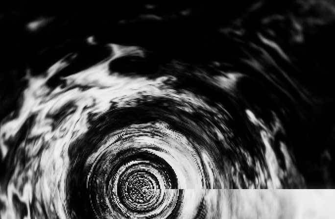
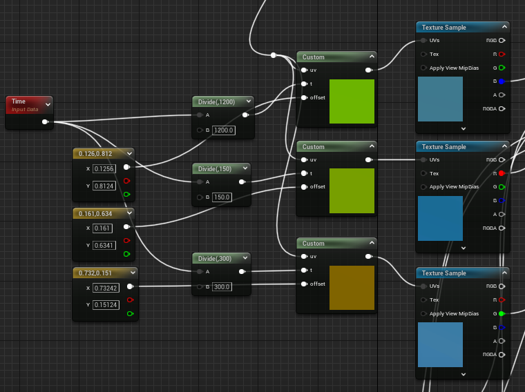
You might wonder why the directly sampled texture looks different in color, this is because the texture has 3 channels for 3 detail-maps
-
R is the high-threshold details
-
G is the mid-threshold details
-
B is the low-threshold details
-
-
Note that I have "averaged out" the brightness within each level of threshold, and also applied a blur to cover up the aliasing issue
-
The original image, by the way, is an algae bloom from some satellite here
-
Instead of sampling all these channels at once, we sample each channel separately and apply a unique offset. Also, we use the ping-pong function to fold the loop the first quadrant of the texture
u += offset.x; v += offset.y + t; u = (u > 0.5 ? u : 1 - u) * 2; v = (v > 0.5 ? v : 1 - v) * 2; -
We simply ping pong thrice each for a different channel
-
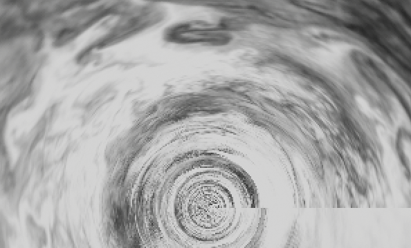
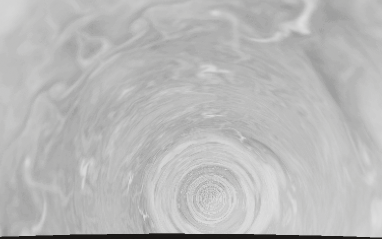
Notice that it is less horrendous if we preview one single channel
- But the issue remains that it still just looks like a rolling piece of paper. To solve this we combine the three channels together
-
I'm not going to go too much into detail for this guy, but I do want to justify for the use of
exp(i.e. one of the slowest arithmetics there is)float h = midfreq - lowfreq; float d = 1 / (1 + exp(-10 * h)); d = floor(d * 10) / 10; float h_ = highfreq /2 - d; float d_ = 1 / (1 + exp(-10 * h_)); d_ = saturate(d_ - 0.1); d_ = floor(d_ * 10) / 10; return lerp(lerp(cloudcol, firecol, d_ * d), skycol, d);-
The simpler logic I started with is
d = midfreq > lowfreq ? 1 : 0;, but the cutoff is sharp and makes the aliasing issue worse -
The
expreplaces the binary cutoff with a logistic curve, and you can adjust the constant for a sharper or blurer cutoff (example using-100 * hinstead) -
Defining
d_based onhighfreq > dwas a hack. I still don't know why I came up with it but it looked better than repeatinghighfreq > midfreqor> lowfreq
-
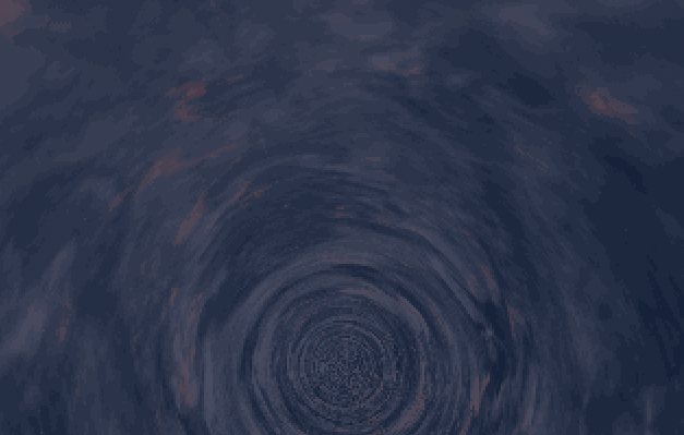
-
Note that the speed at which each channel rolls around the cylinder is different too, so there is some layering effect for the cloud and removes the rotating-paper-feel
-
Before moving on to the next trick, let's just see what we have right now...


§ Submersion
-
This trick is extremely simple
- One issue with having the cylinder start at the origin is that the view rays also converge at the horizon, creating this hole-like "thing" in the middle of the screen
- If we put the cylinder below the surface, then the hole also goes below the surface!
-
We simply use
v.z += submersion;before the projection (herevmeans the view vector, notuv.y)- Using
submersion = 500(5 meters, relative to a 40 meter sphere) we get the following when viewed from a relatively low elevation
- Using
-
But, of course, if we go up the issue shows again, unless we account for camera position in the projection (one of your exercises!)
§ Ellipsing
-
As the name suggests this trick squishes an axis so that the cylinder's "caps" are ellipses instead of circles
-
This is very simple to do as well, as you only need to do
v.z *= 2(before adding submersion from the last section)

§ Fogging
-
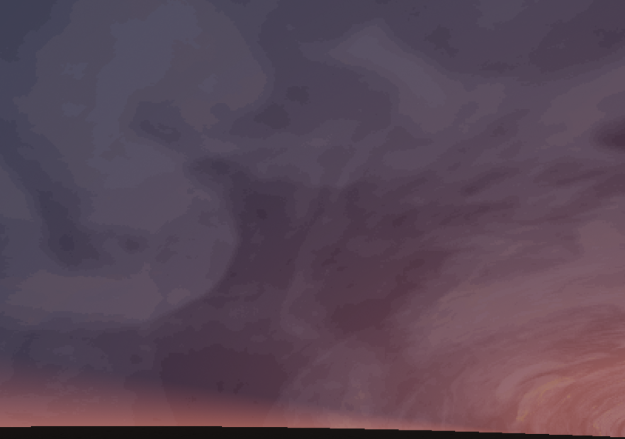
This trick is for hiding clouds at the horizon and potentially creating a smoother look, I settled on the following that doesn't really work well with submersion but has a good side-view
fog=saturate(sin(abs(rho) - 0.7)); fog = fog * fog; fog = fog * fog; fog = fog * fog; fog = max(fog, saturate(h / 5 * R) * 0.1); -
The side view with fog exaggerated
-
Fog breaks down quite a lot when looking from an elevated location
-
... and of course everything breaks down when looking from outside the mesh
A more elaborate solution might use fog to adjust the different cloud frequency samples mentioned above, like decreasing high/mid frequency at angles close to the horizon
§ Water
This last section shows a cheap-ish way to render single layer water reflections based on the cylinder cloud
- In general this technique works for any sky shape sampled with view-direction (cubemap, cylinder, etc.) if you have access to that shader itself
- If you have high quality, low cost reflection, don't bother with this section and just make your sky mesh visible to reflection captures :)
-
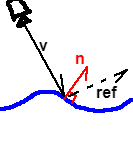
Generally for water shaders there is "some" way to generate a normal vector describing the shape of the water surface at a particular point
- We call this vector
npointing upwards away from the water surface - Computing
nis out of the scope of this walkthrough- It is easy to first generate displacement and then use
ddx(p) x ddy(p)of the modified world position (as long as you're on a modern desktop and the GPU supports such operation) - Feel free to use a normal map, height map, etc. as well
- It is easy to first generate displacement and then use
- We call this vector
-
We can generate an estimation of the view direction (from camera to a point on the water surface)
- This is done by subtracting water surface position from camera position
-
We could then simply reflect this view director against the water surface normal and pass in that to our cloud shader
ref = vn - 2 * dot(vn, n) * n- Do make sure that
vnis against n, as in,dot(vn, n) < 0 - This is automatically true for a top-down game like TP:EW (and if you're under water you would want to switch to a different technique anyway)
- Also make sure
nis already normalized or elsevnwill lenghthen after the reflection
If you implemented parallax, the camera position would also need to be replaced by the water surface position!
-
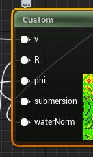
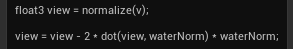
To illustrate how technically simple this technique is, here are the only two changes to the cloud shader
- Passing in the water normal to the cloud shader
- Reflecting the view direction
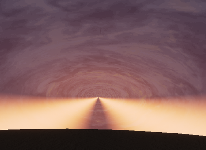
-
And the end product is this
§